Recently I acquired an Elegoo 3D printer from a friend. While I’ve never got interested in 3d printing enough that made me go ahead and buy one, there were certainly projects in the back of my head, just waiting for the right opportunity. One of them was printing some of the objects I modeled for my Shadertoy shaders. The whole challenge was understanding how to convert SDFs into actual meshes that could get sliced and printed. In this text I’m describing my process going through that.
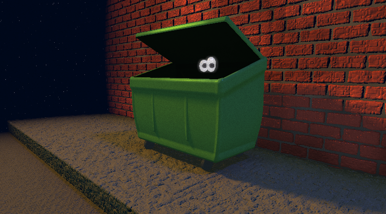
Night Sneaking is a shader I wrote in 2020, displaying a character sneaking out of a trash bin
Coincidentally, just a few days after I got my hands on that printer, someone posted about this project Halfspace on Hacker News:
Halfspace is an experimental IDE for solid modeling with distance fields.
Halfspace is a showcase app for the Fidget kernel, which is used for rasterization and meshing. Within the GUI, images are rasterized in real(ish)-time; models can be exported as either images or triangle meshes:
The modeling part was done, but what drew my attention instantly was the ability to export triangle mesh. Before I could do any research about exporting SDFs to meshes, this just popped out. So I took some time to understand how it works.
SDF and How to Represent a 3D Object
The most common way to represent a 3D object is using a mesh of triangles. That’s how games, cinema, and pretty much all modeling tools deal with. There are exceptions, such as CAD, sculpting software and more modern 3D simulations, meshes are the most used representation of a 3D object in a computer. A mesh is a collection of points in the 3D space (vertices) that are connected to each other usually in the triangle shape. Then from that, the GPU can rasterize or ray-tracing those triangles to form the 2D images seen on the screen.
When I first heard about Shadertoy, around 2017, I was really impressed how people could make complete photo-realistic 3D scenes without using a single mesh. Only using these mathematical functions. That’s what drew me into this world. Then I started reading Inigo Quilez’ blog to understand what SDFs were.
Turns out that in Shadertoy, the most used technique to make those scenes are modeling it with SDFs: Signed Distance Functions, then combining them with CSG (Constructive Solid Geometry). Then using a ray-marching algorithm to get the surface of the SDFs on the screen, and finally applying classic shading techniques on top of that. It’s really elegant and can produce absurd results with just a few lines of heavy-math GLSL fragment shader code:
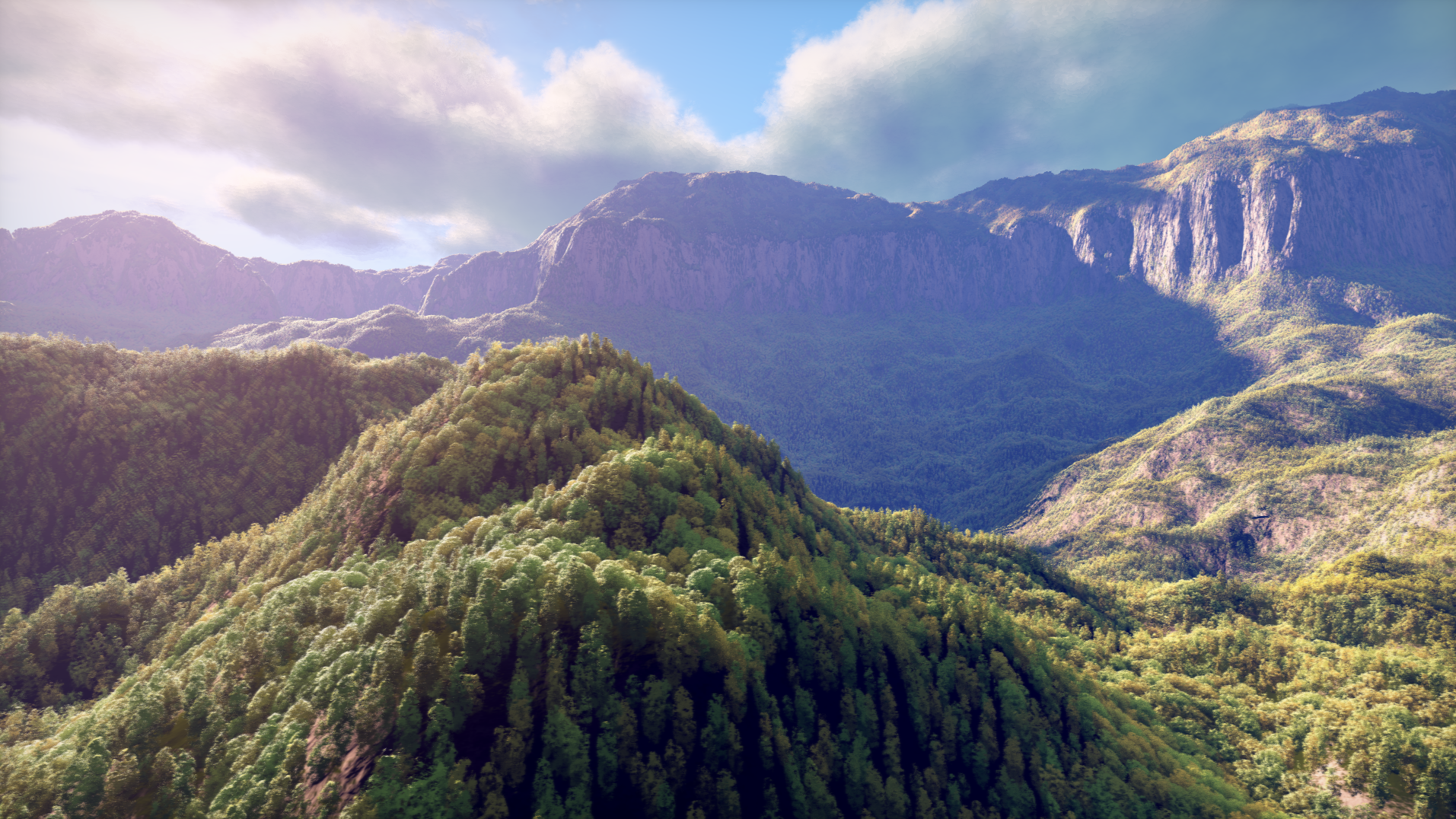
iq’s Rainforest. Ok, it’s around 1k LoC, but it’s all in a single fragment shader!
Fidget uses a similar concept, but in a more mathematical way, called implicit surfaces. Although I’ve been doing SDFs for many years, I never heard about that concept before, but it’s actually pretty much the same thing. It’s a way to define a solid object using a function that accepts a 3d point and returns 0 for when that point is exactly on the surface; returns a positive value when the point is outside the object (it’s usually the distance to the closest point in the surface); and negative when it’s inside the surface. And of course, they can also be combined using CSG operations.
Converting a Pawn
I wanted to start with one of the first SDF scene I implemented on Shadertoy in 2019:
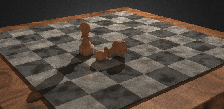
Chess Pawn Board, also rendered here
The SDF code for the pawn itself is just:
object pawn(vec3 p)
{
    float s = sdSphere(p + vec3(0.0, 0.2, 0.0), 0.19);
    float b = sdCappedCylinder(p + vec3(.0, 1.0, .0), vec2(0.24, 0.1));
    float h = sdCappedCylinder(p + vec3(.0, 0.6, .0), vec2(0.11, 0.27));

    float r = sdCappedCylinder(p + vec3(.0, 0.48, .0), vec2(0.205, 0.01));

    float f = opUnion(opSmoothUnion(opSmoothUnion(h, b, 0.4), s, .05), r);

    return object(f, OBJ_PAWN);
}
Just a sphere on the top, a middle cylinder with a thicker cylinder on the bottom, smooth-union to make the round slope and another very short cylinder just under the top. Simple CSG over SDF primitives.
Since I couldn’t find a lot of documentation on Fidget, I asked GLM3.5 to convert that GLSL code into the Rhai code for Fidget. It took an astounding amount of time and tokens to generate it. I think I could probably have done that in less time if I had the docs. But it worked:
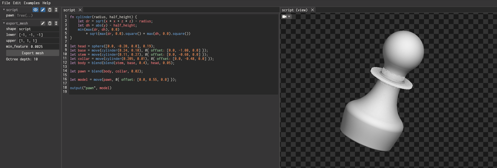
GLM3.5 generated the Rhai code
In the end, the converted code is really similar to the GLSL code.
Halfspace has a visual programming environment that uses nodes to create primitives and operations, but also has a Script node. In fact, I could do the whole model without any code, but I already have the code. In the end, I need the export_mesh node to do all the magic. I just had to specify which node it should use the output from, and select min_feature, which makes the object more dense and detailed.
That generated this model:
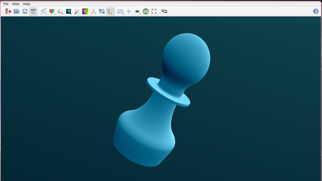
The pawn STL model looks pretty good
So I went to the slicing software, Cura, imported the mesh and messed with the settings:
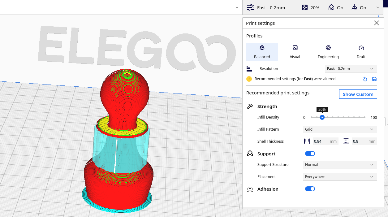
Some supperts were needed for the middle ring
I also had to change the scale to 5,000%. As it was showing 10,000% when I imported the model, somehow. In the end I wish I picked a slightly smaller scale here, as the pawn turned out a bit bigger than I wished. Nonetheless, I enjoyed the result:
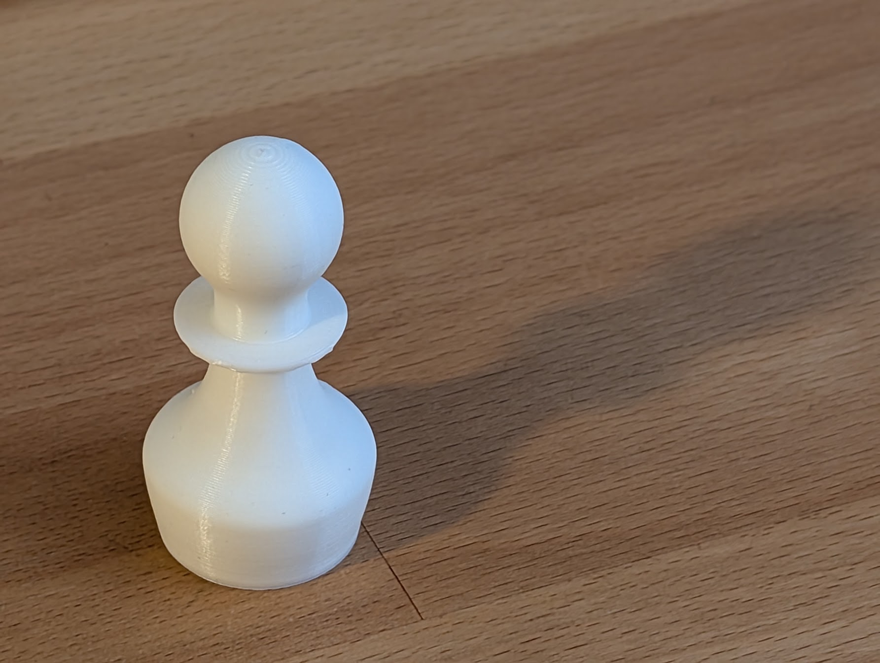
The pawn I modeled many years ago with mathematical functions
Only about 40 minutes printing, and the pawn actually feels pretty solid.
All Goes to Trash
Then I started working on the trash bin from this shader I’m really proud of:
The main code for the bin model is:
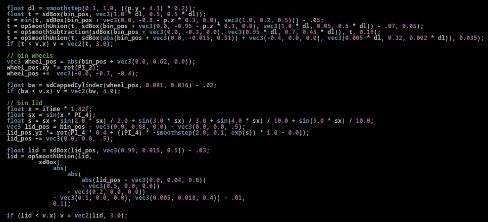
A bunch of boxes composed together
It’s a bit messy, but it’s also more involved than the pawn. I wanted to implement this by hand on Fidget, so I asked DeepSeek to generate documentation from the source-code. Turns out it was a good idea, and I think it’s a fair use of AI: asking it to generate some docs from a project’s source for me to use, when that’s nonexistent.
I wrote that over five years ago, so I didn’t instantly remember how I composed that model. It starts with a smoothstep, but I realized that Fidget doesn’t have a smoothstep function. So I started writing my own smoothstep, which relied on a clamp, that also didn’t exist. I tried to implement it with if-else rather than a min-max, and it just didn’t compile, complaining that I could not compare values.
I went back to Matt’s texts about Halfspace and Fidget and found that Fidget generates a whole bytecode with math operations, in order to simplify the SDFs. Still not sure exactly why, but that’s why I couldn’t compare values. That’s when I started to understand one fundamental difference between my shader SDFs and the Implicit Surfaces described here. When using the raymarching algorithm on a fragment shader, we have a specific parameter that is passed on to my functions that is the current point in which I’m testing. It finds the surface point by marching away from the lens incrementally, and we get to test when we are within the solid or not (using the SDF). The cool part is that I can also use that point as the surface point to change the object by warping the space. With Fidget’s API, you have access that point with the global x, y, and z. But since they’re not passed as a parameter the implicit surface function, it would be a bit too messy to play with.
And warping the space is a trick that I use in a few places to modify the primitives. For example, that’s how I add this curve-like to the body of the bin. Removing the variation caused by the smoothstep on the first line of my SDF (by making dl = 1), causes the bin:
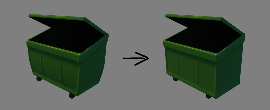
I find that curve sexy
The variable height of the bin (back vs front) is also done by distorting the space. I’d have to change the global values for x, y and z a few times throughout the code to make that work, and that made me unhappy. So I looked for alternatives.
sd2mesh
Then I started researching, like I should’ve done before, and found another project that does specifically what I needed. sdf2mesh can take an SDF function in GLSL, with a similar input and output to what I’m used to. I just had to remove all the code for shading and the raymarching algorithm, close the lid and change my map function into float sdf(vec3 p), as specified by the tool.
The final code was this:
#version 450 core

const float PI_2 = 1.57079632679489661923;
const float PI_4 = 0.785398163397448309616;

const float iTime = 0.5;
const vec3 bin_disp = vec3(0.0, -0.72, 1.0);
const float MAX_DIST = 9.0;

mat2 rot(float phi)
{
    float c = cos(phi);
    float s = sin(phi);
    return mat2(vec2(c, -s), vec2(s, c));
}

float sdBox(vec3 p, vec3 b)
{
    vec3 d = abs(p) - b;
    return length(max(d, 0.0));
}

float sdCappedCylinder(vec3 p, float h, float r)
{
    vec2 d = abs(vec2(length(p.xz), p.y)) - vec2(h, r);
    return min(max(d.x, d.y), 0.0) + length(max(d, 0.0));
}

float opSmoothSubtraction(float d1, float d2, float k)
{
    float h = clamp(0.5 - 0.5 * (d2 + d1) / k, 0.0, 1.0);
    return mix(d2, -d1, h) + k * h * (1.0 - h);
}

float opSmoothUnion(float d1, float d2, float k)
{
    float h = clamp(0.5 + 0.5 * (d2 - d1) / k, 0.0, 1.0);
    return mix(d2, d1, h) - k * h * (1.0 - h);
}

float sdf(vec3 p)
{
    float v = MAX_DIST;

    // trash bin
    vec3 bin_pos = p + bin_disp;
    if (sdBox(bin_pos, vec3(1.3, 1.5, 0.6)) < v)
    {
        float dl = smoothstep(0.3, 1.0, ((p.y + 4.1) * 0.2));
        float t = sdBox(bin_pos, vec3(1.0 * dl, 0.5, 0.5 * dl));
        t = min(t, sdBox(bin_pos + vec3(0.0, -0.8 - p.z * 0.3, 0.0), vec3(1.0, 0.2, 0.5))) - .05;
        t = opSmoothUnion(t, sdBox(bin_pos + vec3(0.0, -0.95 - p.z * 0.3, 0.0), vec3(1.0 * dl, 0.05, 0.5 * dl)) - .07, 0.05);
        t = opSmoothSubtraction(sdBox(bin_pos + vec3(0.0, -0.3, 0.0), vec3(0.95 * dl, 0.7, 0.45 * dl)), t, 0.19);
        t = opSmoothUnion(t, sdBox(abs(bin_pos + vec3(0.0, -0.015, 0.51)) + vec3(-0.4, 0.0, 0.0), vec3(0.005 * dl, 0.32, 0.002 * dl)), 0.035);
        v = min(v, t);

        // bin wheels
        vec3 wheel_pos = abs(bin_pos + vec3(0.0, 0.62, 0.0));
        wheel_pos.xy *= rot(PI_2);
        wheel_pos += vec3(-0.0, -0.7, -0.4);
        float bw = sdCappedCylinder(wheel_pos, 0.081, 0.016) - .02;
        v = min(v, bw);

        // bin lid
        float x = iTime * 1.82f;
        float sx = sin(x * PI_4);
        float s = sx + sin(2.0 * sx) / 2.0 + sin(3.0 * sx) / 3.0 + sin(4.0 * sx) / 10.0 + sin(5.0 * sx) / 10.0;
        vec3 lid_pos = bin_pos - vec3(0.0, 0.88, 0.0) - vec3(0.0, 0.0, .5);
        lid_pos.yz *= rot(PI_4 * 0.4 + ((PI_4) * -smoothstep(2.0, 0.1, exp(s)) * 1.0 - 0.0));
        lid_pos += vec3(0.0, 0.0, .5);
        float lid = sdBox(lid_pos, vec3(0.99, 0.015, 0.5)) - .03;
        lid = opSmoothUnion(lid,
                 sdBox(
                     abs(
                         abs(
                             abs(lid_pos - vec3(0.0, 0.04, 0.0))
                             - vec3(0.5, 0.0, 0.0))
                         - vec3(0.2, 0.0, 0.0))
                     - vec3(0.1, 0.0, 0.0), vec3(0.005, 0.018, 0.4)) - .01,
                     0.1);
        v = min(v, lid);
    }

    return v;
}

void main() {}
Then I ran with:
./target/release/sdf2mesh --glsl ./trashbin/shader.frag --resolution 512 --mesh ./trashbin/bin.stl --bounds 5
That generated a nice STL model. I tried bumping the resolution to 1024 and it looked even better:
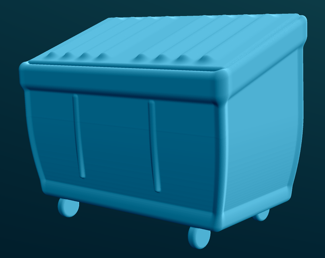
That’s a high-poly model
There are some weird artifacts such as a section line, but I thought it would be fine. Then I imported into the slicer:
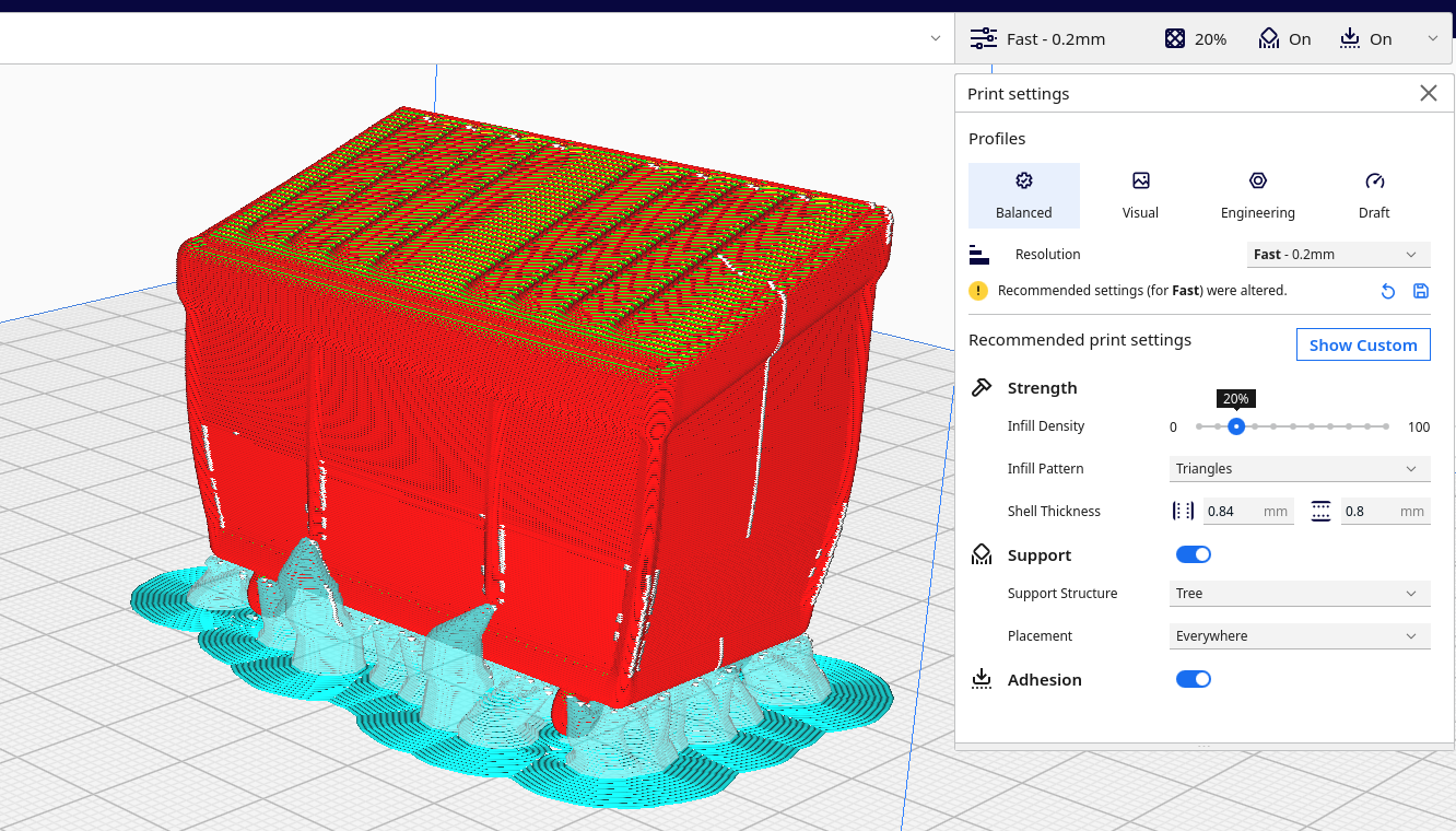
high-slices too
It complains that the model is not water-tight, and I can see other artifacts here, but interestingly enough, not the one in the STL model itself. I gave it a got and printed it with 2,714.22% scale. And after around one hour, I was left with this beautiful small trash bin:
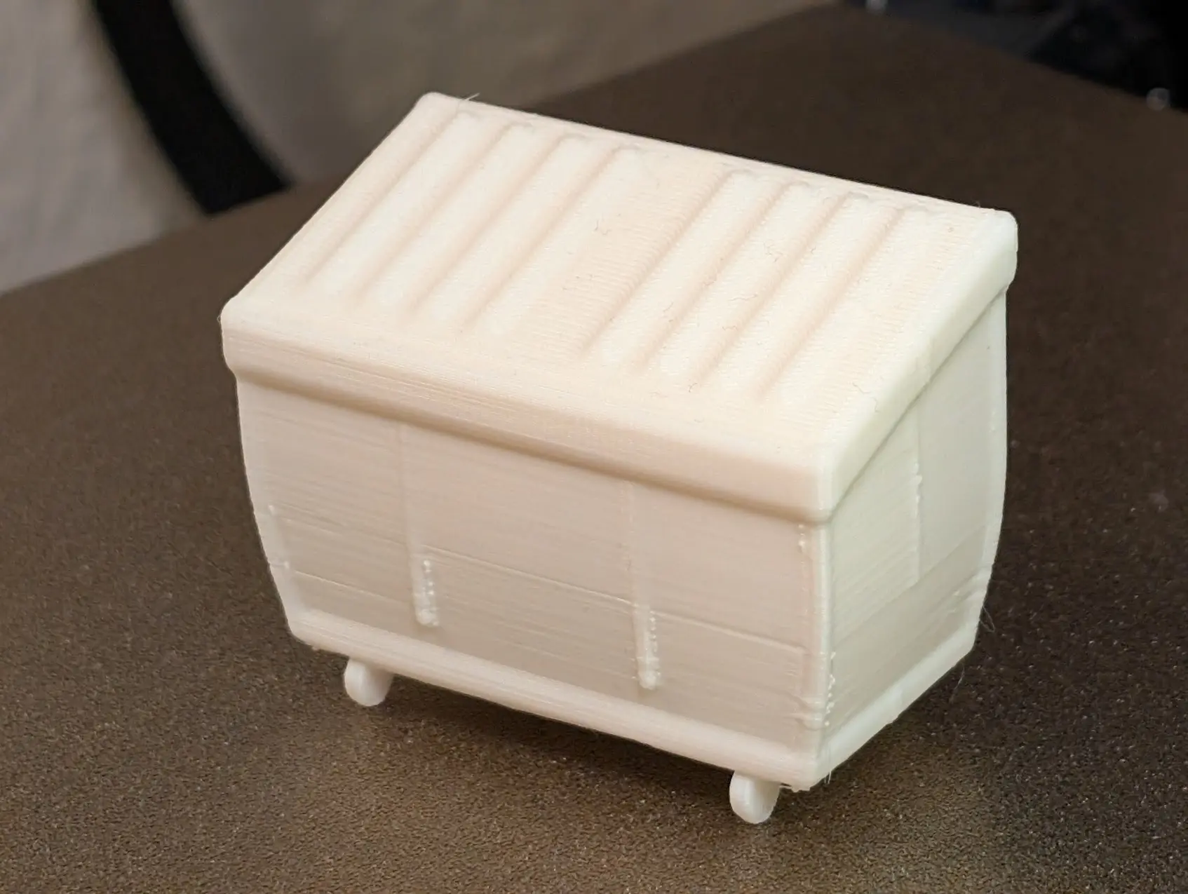
I only had white filament
Some of the artifacts are still seen here. The artifacts are definitely visible there, but I imagine that generating it with bigger resolution, then slicing it in a bigger scale and with finer resolution could fix these artifacts. Overall, I really enjoy the result.
Eventually I want to do this acetone technique to smooth the models:
Conclusion
That was a nice way to start my 3d printing journey. I do think I should have done a proper research before jumping on Halfspace and Fidget. They are pretty cool tools, just not the best one for my problems. Nonetheless, this mistake made me learn more about Implicit Surfaces, SDFs and 3D in general. Next time I might want to implement my own tool to convert SDFs into meshes, exploring the actual algorithms behind it.
Also, the initial idea was to make a working lid for the bin, so I had a functional small storage box. Not sure yet how I’d do that, if I could print a simple hinge, already in place. That’ll be an interesting following project.
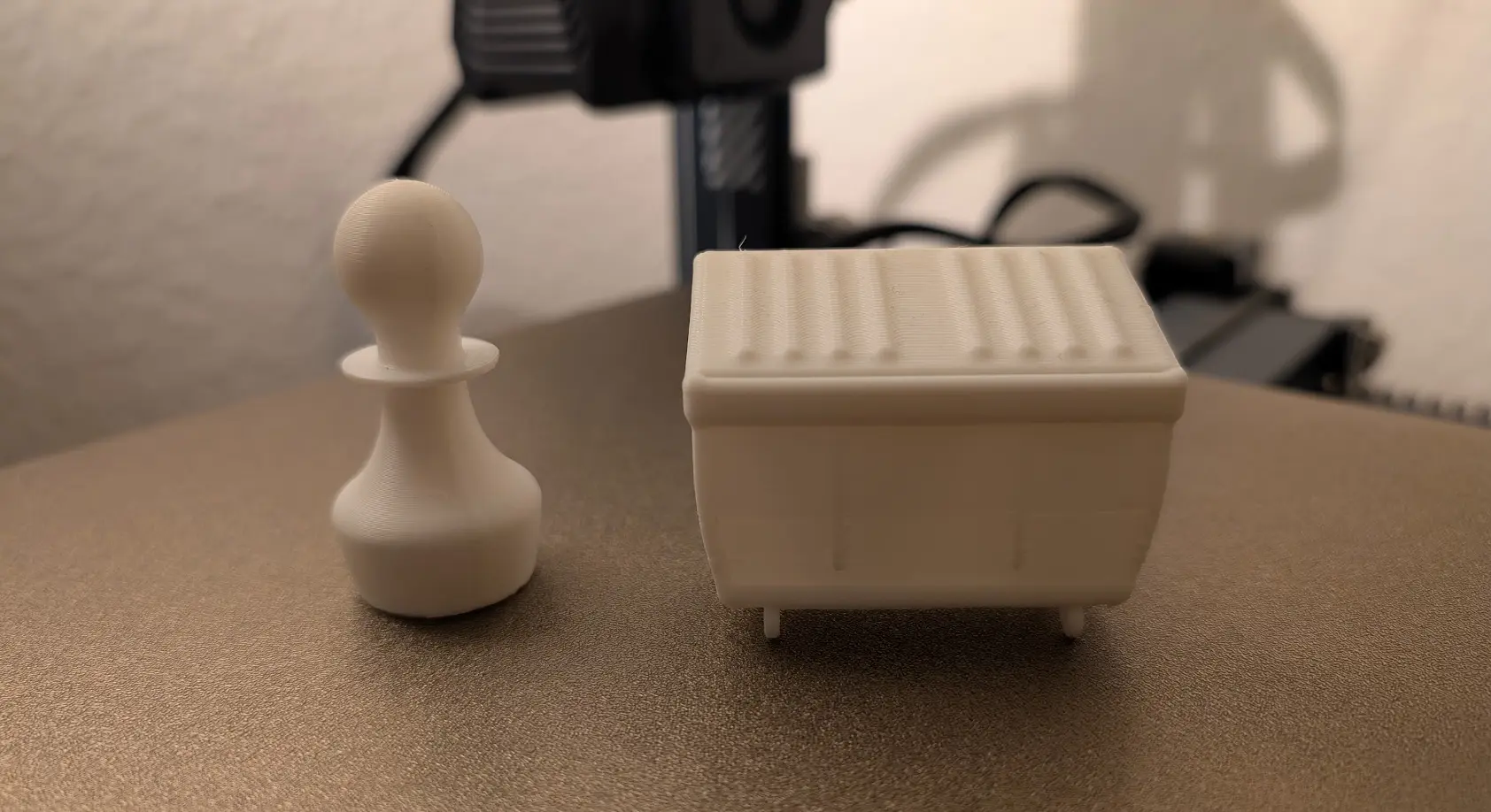
My first two 3d printed models ever